Conventional, or manual, milling machines are primarily used to machine flat and angled surfaces by feeding a workpiece into a rotating cutting tool to remove material. They are also commonly used to position work more accurately for the same type of holemaking operations than can be accomplished with a drill press. By combining these operations, components can be machined to countless desired shapes.
Speeds and Feeds for Milling Operations
Calculating spindle RPM for milling operations is the same as calculating RPM for drill press operations. Use the standard formula RPM = 3.82 X CS / D where CS = cutting speed in surface feet per minute and D = diameter of the cutting tool. Milling machines also use IPM (inches per minute) for power quill feed settings. To calculate IPM, the following formula is used: IPM = FPT X N X RPM, where FPT = feed per tooth, N = number of teeth, or flutes, of the cutting tool, and RPM = spindle RPM.
Project 1 - Step Block
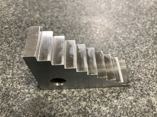
- Square the block. Squaring a workpiece means machining the sides of a workpiece perpendicular and parallel to each other.
- Use an edge finder to find a reference edge. When using a collet it is important not to over-tighten or the hollow edge finder shank can be damaged.
- Use center drill for X = 0.625, Y = 0.625
- Use drill size 27/64 or 0.421875 for ½ - 13 tap
- Determine the correct tap drill size.
- Be sure to apply cutting oil of a type appropriate for the material being tapped.
- Start tapping the hole using a dead center and a taper tap.
- Continue tapping the hole with a plug tap.
- Finish tapping the hole with a bottoming tap.
- We start to cut the steps along the 3.00 length. Bring down the quill to set cut depth and lock. We will use DRO to finish mill all of these steps.
- If the horizontal spindle surface grinder is used for the finish, leave extra 0.005 for the dimensions.
Project 2 - 123 Block
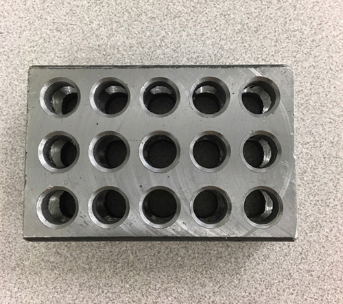
Holemaking operations are performed on the vertical milling machine. The work can be precisely moved using the table and saddle movements to align the work with the spindle. The digital readout (DRO) can also be used to create precise spacing between hole locations or between edges and hole locations. It is a good practice to lock both saddle and the table before creating holes to ensure that neither moves during the actual machining operation.
When the location of a hole from a reference edge is more critical, an edge finder can be used to very accurately find a reference edge. Carefully move the table to bring the edge finder in contact with the edge of the workpiece. Continue to slowly move the table. Notice that the tip will begin to run more true as the workpiece pushed the tip into alignment with the shank. When the tip "kicks," the position of the center of the edge finder (and the machine spindle) is one-half of the edge finders tip diameter from the edge of the workpiece. Every time you remove the workpiece from the workholding device, make sure that you know the reference '0" position from the edge of the workpiece so you can reestablish the coordinate locations from the same edge. Follow these steps to machine holemaking operations:
- Square the block.
- Locate the first hole with edge finder.
- A center drill or spot drill is used to create a more positive starting point for a twist drill. Retract the quill frequently to clear chips from the point.
- After spotting, the next step in the process is drill a pilot hole. A pilot hole is often drilled before the larger drill bit is used. Drill pilot holes on both sides for 2.0 and 3.0.
- Drill 0.375 and 0.438 holes
- Finally, use a countersink 60-degree to chamfer the opening of holes.
Project 3 - Clamp
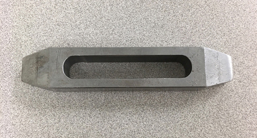
A pocket is an internal part feature machined into the surface of a workpiece. Pocket location and size can be controlled by using the DRO to monitor table and saddle movements. Follow these steps to machine a pocket:
- Square the block.
- Determine endmill diameter. I use endmill diameter 0.5 for this project.
- Create a coordinate map. The drawing above shows the X- and Y- axis coordinates of the center point locations of the cutting tool. For example, the center point of the pocket will be 0 for Y-axis. The endmill will cut 0.5 diameter. But we need to create 0.540 pocket. So we need to move the saddle 0.020 away from the column along the Y-axis to 0.480 and 0.020 toward from the column along the Y-axis to 0.520. Also, the radius of the endmill must be taken into consideration when calculating these coordinates. So when we mill the length of the pocket, we move the table from left to right along the X-axis. Use an edge finder to establish the reference "0" position from the edge of the workpiece. We will start to mill the length of the pocket from X-axis coordinate 1.25 which equals 1 + 0.25 (the radius of the endmill) to 3.75 which equals 4 - 0.25 as it is shown in the drawing above.
- Mill the pocket with 0.5 diameter which is the same size as the endmill diameter. Establish the length of the pocket 3.0.
- Mill the width of the pocket using Y-axis coordinate 0.480 and 0.520.
- One thing about milling the pocket is that the bottom of the pocket will be smaller than the top. So you need to flip the part and finish the backside of the pocket. Every time you remove the workpiece from the workholding device, make sure that you know the reference "0" position from the edge of the workpiece so you can reestablish the coordinate locations from the same edge.
- For milling the 15 degree angle, we use a fixture to position our workpiece at the desired angle for angular milling operations.
Project 4
- Tools:
- 4-flute HSS endmill ½
- Angle block or V-block
- Dimension: 1.490”W X 1.875”L X 0.990”H
- 700 RPM, 10 IPM
- Material: cold roll steel or mild steel
- Milling Operations:
- Square the block
- Cut the center slot
- Cut the step
- Mill the angle
- Machine Setup
- Use parallels to raise the workpiece in the vise.
- Load the workpiece into the vise.
- Tighten the vise.
- Assure there is no debris on the arbor and the spindle.
- Load a tool into the spindle.
- Square the block
- Determine the Feeds and Speeds for the squaring operation.
- Set the Feeds and Speeds on the milling machine.
- Face off before square the block.
- Remove the necessary amount of material to square the top of the part.
- Use a micrometer to check for taper in the squared part.
- Use a micrometer to check for parallelism in the squared part.
- Fix a tapered part.
- If the horizontal spindle surface grinder is used for the finish, leave extra 0.005 for the dimensions.
- Cut the center slot
- Cut the step
- Angular milling
- Use V-block or angle block to mill the angular part 45 degree.
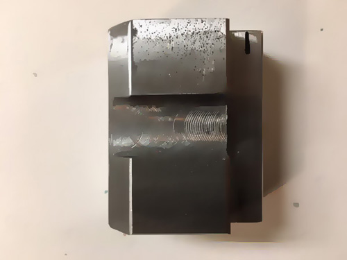
Project 5
- Tools:
- Roughing 4-flute HSS endmill:5/8
- Finishing 4-flute HSS endmill:1/2
- Center drill #1 and #3
- Chamfer endmill
- HSS twist drill
- Reamer
- Tap drill #7
- Boring Head
- Dimension: 1.875”W X 2.50”L X 1.375”H
- 700 RPM, 10 IPM
- Material: cold roll steel or mild steel
- Milling Operations:
- Square the block
- Center drill
- Drill 4 holes
- Ream 2 holes
- Bore a thru hole
- Countersink
- Cut the first step
- Cut the second step
- Cut the center slot
- Tap drill
- Machine Setup
- Use parallels to raise the workpiece in the vise.
- Load the workpiece into the vise.
- Tighten the vise.
- Assure there is no debris on the arbor and the spindle.
- Load a tool into the spindle.
- Square the block
- Determine the Feeds and Speeds for the squaring operation.
- Set the Feeds and Speeds on the milling machine.
- Face off before square the block.
- Remove the necessary amount of material to square the top of the part.
- Chatter and squealing noises indicate that spindle speed is too high. Very fine chips indicate that feed is too slow. Very thick chips that do not curl indicate the feed is too fast. When machining steels with an HSS cutting tool, brown or blue chips also indicate that feed is too high.
- Use a micrometer to check for taper in the squared part.
- Use a micrometer to check for parallelism in the squared part.
- Fix a tapered part.
- If the horizontal spindle surface grinder is used for the finish, leave extra 0.005 for the dimensions.
- Center drilling
- Use an edge finder to locate four holes.
- Center drill each of the 4 holes on the part. Use ¼ of the normal RPM. A center drill is used to create a more positive starting point for a twist drill.
- Drill the two holes:
- Use drill size 0.115 if use the reamer
- The depth stop on the mill quill can be used to set the depth.
- Use peck drilling to clear chips from the point.
- Use a gage pin to check the full-diameter depth of a hole.
- Ream the two holes:
-
Reaming is the process of finishing a hole to a precise size with a smooth finished surface. When a hole must be machined to a more accurate diameter or surface finish than can be produced by drilling, a reaming operation may be selected to meet requirements. To properly ream a hole, a twist drill is selected that is slightly smaller than the reamer:
- 0.010” undersize for a hole up to ¼”
- 0.015” undersize for a hole up between ¼” – ½”
- 0.025” undersize for a hole between ½” and 1-1/2”
- The depth stop on the mill quill can be used to set the depth.
- Use power feed transmission engagement crank, quill feed selector knob, and feed control lever to engage the power feed.
- Be sure to apply cutting oil of a type appropriate for the material being reamed.
- Use a speed about 50% to 60% of that used for drilling the same material.
- Complete the reaming operation.
- Never turn the reamer backward.
- Ream down to the bottom until the depth stop.
- Then withdraw the reamer from the hole.
- Use a gage pin to check the full-diameter depth of a hole
-
Reaming is the process of finishing a hole to a precise size with a smooth finished surface. When a hole must be machined to a more accurate diameter or surface finish than can be produced by drilling, a reaming operation may be selected to meet requirements. To properly ream a hole, a twist drill is selected that is slightly smaller than the reamer:
- Drill a tap hole
- Drill the tapped hole.
- The depth stop on the mill quill can be used to set the depth.
- Use peck drilling to clear chips from the point.
- Use a gage pin to check the full-diameter depth of a hole.
- Drill a thru hole
- Use 250 RPM for drilling.
- Use peck drilling to clear chips from the point.
- Pilot hole is drilled before the larger drill bit is used. The pilot hole creates relief for the dead center and reduces the pressure required to feed the drill into the work.
- Boring uses a single-point cutting tool to enlarge an existing hole. Some advantages of boring over other holemaking operations are that any desired hole size can be machined and large-diameter holes that are beyond the range of drills and reamers can be produced. Another benefit of boring is the ability to adjust the location of a hole since the boring tool will not follow the existing hole like a drill.
- Calculate and set an appropriate spindle speed. Because boring bars are less rigid than other holemaking tools, spindle speeds will need to be reduced by one-fourth to one-third of the calculated RPM for a drill of the same diameter as the diameter to be bored. This will help reduce excessive vibration and chatter.
- Machine a check cut with the boring bar.
- Use a dial indicator to adjust the boring bar.
- Bore hole to final size.
- Bore a thru hole
- Boring uses a single-point cutting tool to enlarge an existing hole. Some advantages of boring over other holemaking operations are that any desired hole size can be machined and large-diameter holes that are beyond the range of drills and reamers can be produced. Another benefit of boring is the ability to adjust the location of a hole since the boring tool will not follow the existing hole like a drill.
- Calculate and set an appropriate spindle speed. Because boring bars are less rigid than other holemaking tools, spindle speeds will need to be reduced by one-fourth to one-third of the calculated RPM for a drill of the same diameter as the diameter to be bored. This will help reduce excessive vibration and chatter.
- Machine a check cut with the boring bar.
- Use a dial indicator to adjust the boring bar.
- Bore hole to final size.
- Cut the first step
- Cut the second step
- Cut the center slot
- Tap drill
- Countersink
- Use ¼ of the drilling RPM.
- Determine the correct tap drill size.
- Be sure to apply cutting oil of a type appropriate for the material being tapped.
- Start tapping the hole using a dead center and a taper tap.
- Continue tapping the hole with a plug tap.
- Finish tapping the hole with a bottoming tap.
- When tapping by hand, advance the tap about one half to one full turn at a time. The tap should then be backed out by half a turn before continuing. This helps break the chip being formed as it cuts. Not backing the tap up will often cause the tap to bind in the hole and break.
- When tapping under power on a vertical milling machine, use a low RPM, leave the quill unlocked, use both the forward and reverse motions of the motor.
- A tappping head is a specially designed tool that allows the spindle to be run to drive taps. A tapping head contains an adjustable clutch that limits torque to prevent tap breakage. It also contains a mechanism that reverses tap direction when the quill is raised to retract the tap from the hole.