There is no standardized format for writing a CNC program that is compatible with all machine control models. Each MCU manufacturer has developed its own unique programming format. Each one has minor differences, but the principles contained in the context of a program are the same among them all. These programs that I have written for school projects will relate most closely to Fanuc-type controllers specifically Haas and Doosan; however, the principles may be applied to any manufacturer's programming format (see the specific machine's programming manual).
Free download from Haas:
Free download from Doosan:
Free download from Mori Seiki:
Free download from Okuma:
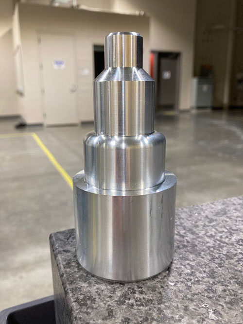
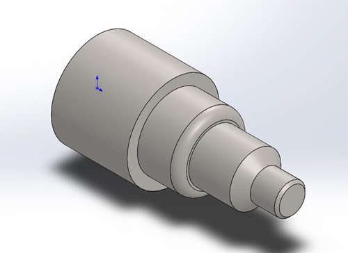
I have several projects per semester. By the end of the semester, I have created many programs and machined the entire things and that really is inspirational. Here are some of the projects I have done in the shop.
Rough & Finish
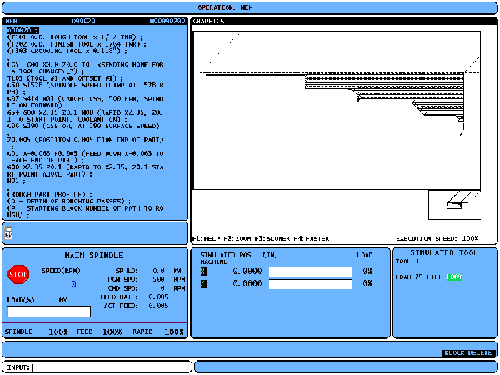
The G71 Roughing cycle will rough out material on a part defining the finished part shap. The G70 Finishing cycle can be used to finish cut paths that are defined and roughed out with stock removal cycles G71. After execution of the Q block, a rapid (G00) is executed returning the machine to the start position that was saved earlier during G70 initialization. The program then returns to the block following the G70 call.
Groove & Thread
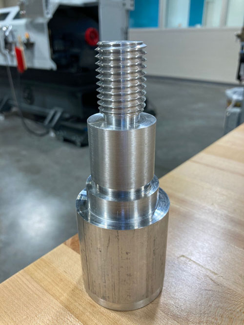
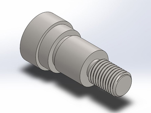
The G75 canned cycle can be used for grooving an outside diameter with a chip break. The G76 canned cycle can be used for threading both straight or tappered (pipe) threads.
For Haas CNC Lathe Machines
%
O00021
(PROGRAMMER: FRANCIS NGUYEN)
(VERSION: 2020)
(STOCK 2.5" O.D.)
(T0101 O.D. ROUGH TOOL x 1/32 TNR)
(T0202 O.D. FINISH TOOL x 1/64 TNR)
(T0303 GROOVING TOOL x 0.118")
(T0404 O.D. THREADING TOOL)
(T0505 PARTING TOOL x 0.118")
(T0606 STOP BAR)
(T0707 CENTER DRILL #2)
(BAR STOP)
G53 G00 X0.0 Z0.0 T0 (SENDING HOME FOR A TOOL CHANGE)
T0606
G55 G00 X0.0 Z0.02
M00
Z0.1
X5.0 Z1.0
G28 U0.0
M01
T0101 (TOOL #1 AND OFFSET #1)
G50 S1000 (SPINDLE SPEED CLAMP AT 1000 RPM)
G96 S500 M03 (CSS ON, AT 500 SURFACE SPEED, SPINDLE ON FORWARD)
G55 G00 X2.6 Z0.1 M08 (RAPID X2.6, Z0.1 TO START POINT, COOLANT ON)
G01 Z0.0 F0.01
X-0.063 (FEED DOWN X-0.063 TO FACE END OF PART)
Z0.1
G00 X5.0 Z1.0 M09 (RAPID TO X2.6, Z0.1 START POINT ABOVE PART, COOLANT OFF)
G28 U0. (SENDING HOME FOR A TOOL CHANGE)
M05 (SPINDLE STOP)
M01 (OPTIONAL STOP COMMAND)
(CENTER DRILL USING LIVE TOOL)
T0707 (Tool 5 Offset 5)
G98 (Feed per minute)
M154 (Engage C-Axis)
G97 M133 P1000 (Live Tool Drive Forward/Live Tool Spindle Speed)
G55 G00 X0. C0. Z0.25 M08 (Rapid to Initial Start Point)
G81 Z-0.125 R-0.15 F1.0 (G81 Drilling Cycle)
G80 G00 Z0.25 M09
M155 (Disengage C-Axis)
M135 (Live Tool Drive Stop)
G28 H0 (Return C-Axis to Home Position)
G00 X5. Z1.0
G99 (Feed per revolution)
G28 U0. (SENDING HOME FOR A TOOL CHANGE)
M01
(BAR STOP)
T0606
G54 G00 X0.0 Z0.0
M00
Z0.1
X5.0 Z1.0
G28 U0.0
M01
(ROUGH PART PROFILE USING TAILSTOCK)
M21 (TAILSTOCK ADVANCE)
T0101 (TOOL #1 AND OFFSET #1)
G50 S1000 (SPINDLE SPEED CLAMP AT 1000 RPM)
G96 S500 M03 (TURN ON CSS TO 500)
G54 G00 X2.6 Z0.1 M08 (RAPID TO X2.6, Z0.1 START POINT ABOVE PART)
(D - DEPTH OF ROUGHING PASSES)
(P - STARTING BLOCK NUMBER OF PATH TO ROUGH)
(Q - ENDING BLOCK NUMBER OF PATH TO ROUGH)
(U - AMOUNT OF MATERIAL TO BE LEFT ON DIA)
(W - AMOUNT OF MATERIAL TO BE LEFT ON FACES)
G71 P100 Q200 U0.01 W0.005 D0.05 F0.01 (G71 ROUGH CYCLE)
N100 G42 G00 X0.72 (PNN START #100, RAPID X0.72, CUTTER COMP. ON)
G01 Z0.0 F0.005 (G71 PART GEOMETRY)
X0.82 (POINT 1)
X1. Z-0.09 (POINT 2)
Z-1.5 (POINT 3)
X1.45 (POINT 4)
Z-3. (POINT 5)
X1.7 (POINT 6)
Z-3.5 (POINT 7)
X1.95 (POINT 8)
Z-4.425 (POINT 9 EXTEND 0.125)
N200 G40 G00 X2.6 M09 (QNN END #200, CANCEL CUTTER COMP., FEED X TO 2.6, COOLANT OFF)
G00 X5.0 Z1.0
G28 U0. (SENDING HOME FOR A TOOL CHANGE)
M01 (OPTIONAL STOP COMMAND)
(FINISH PART PROFILE)
T0202 (TOOL #2 AND OFFSET #2)
G50 S1200 (SPINDLE SPEED CLAMP AT 1200 RPM)
G96 S600 M03 (TURN ON CSS TO 600)
G54 G00 X2.6 Z0.1 M08 (RAPID TO X2.6, Z0.1 START POINT ABOVE PART)
G70 P100 Q200 (DEFINE A G70 FINISH PASS OF PART GEOMETRY)
G00 X5.0 Z1.0
G28 U0. (SENDING HOME FOR A TOOL CHANGE)
M01 (OPTIONAL STOP COMMAND)
(GROOVING CYCLE)
T0303
G97 S400 M03
G54 G00 X1.6 Z0.1 M08
Z-1.418 (1.30 + 0.118 GROOVING TOOL = 1.418)
(I - X AXIS PECKING DEPTH INCREMENT, RADIUS VALUE)
(K - Z AXIS SHIFT INCREMENT BETWEEN PECKING CYCLES)
G75 X0.750 Z-1.5 I0.05 K0.1 F0.005
G00 X1.8
Z-2.918 (2.800 + 0.118 GROOVING TOOL = 2.918)
G75 X1.250 Z-3.0 I0.05 K0.1 F0.005
G00 X2.6 M09
X5.0 Z1.0
G28 U0. (SENDING HOME FOR A TOOL CHANGE)
M01
(THREADING CYCLE)
T0404
G97 S400 M03
(SINGLE DEPTH = 0.61343 / TPI)
(SINGLE DEPTH = 0.61343 / 8 = 0.0767)
(X START POINT = MAJOR DIA. + 2 X SINGLE DEPTH)
(X START POINT = 0.9905 + 2 X 0.0767 = 1.1439)
(PITCH = 1/ TPI)
(PITCH = 1/ 8 = 0.125)
G54 G00 X1.1439 Z0.25 M08 (X START POINT, Z START POINT)
(K - THREAD HEIGHT, RADIUS VALUE)
(# OF THREADING PASSES = [72 X PITCH] + 7)
(D - FIRST PASS CUTTING DEPTH)
(D = SINGLE DEPTH / OF THREADING PASSES)
(D = 0.0767 / SQRT OF 16 = 0.0192)
(F - 1/TPI)
(F = 1/ 8 = 0.125)
(X - MIN MINOR DIAMETER)
(Z - THREAD LENGHT)
G76 X0.8206 Z-1.3 K0.0767 D0.0192 F0.125 (16 PASSES)
G00 X5.0 Z1.0 M09
G28 U0. (SENDING HOME FOR A TOOL CHANGE)
M00
(PARTING PART)
M22 (TAILSTOCK RETRACT)
T0505
G50 S800 (SPINDLE SPEED CLAMP AT 800 RPM)
G96 S400 M03 (TURN ON CSS TO 400)
G54 G00 X2.6 Z-4.418 M08 (4.30 + 0.118 PARTING TOOL = 4.418)
G01 X-.02 F0.002 M36 (PARTS CATCHER ON)
G00 X2.6 M09
M00
X5.0 Z1.0 M37 (PARTS CATCHER OFF)
G28 U0. (SENDING HOME FOR A TOOL CHANGE)
M05 (SPINDLE STOP)
M30 (END OF PROGRAM AND RESET)
%
For Doosan CNC Lathe Machines
%
O0001
(PROGRAMMER: FRANCIS NGUYEN)
(VERSION: 2021)
(STOCK 2.5" O.D.)
(T0101 O.D. ROUGH TOOL x 1/32 TNR)
(T0202 O.D. FINISH TOOL x 1/64 TNR)
(T0303 GROOVING TOOL x 0.118")
(T0404 O.D. THREADING TOOL)
(T0505 PARTING TOOL x 0.118")
(T0606 STOP BAR)
(T0707 CENTER DRILL #2)
#100 = 4.300 (PART LENGTH)
#101 = 2.500 (STOCK DIA)
#102 = #101 + 0.1(STOCK DIA + 0.1)
#103 = #100 + 0.118 (PART LENGTH CUTOFF)
(BAR STOP)
T0606
G55 G00 Z0.02 X0.0
M00
Z0.1
X5.0 Z1.0
G28 U0.0
M01
T0101 (TOOL #1 AND OFFSET #1)
G50 S1000 (SPINDLE SPEED CLAMP AT 1000 RPM)
G96 S500 P11 M03 (CSS ON, AT 500 SURFACE SPEED, MAIN SPINDLE ON)
G55 G00 X#102 Z0.1 M08 (RAPID X2.6, Z0.1 TO START POINT, COOLANT ON)
G01 Z0.0 F0.01
X-0.063 (FEED DOWN X-0.063 TO FACE END OF PART)
G00 X#102 Z0.1 M09 (RAPID TO X2.6, Z0.1 START POINT ABOVE PART, COOLANT OFF)
X5.0 Z1.0
G28 U0.0 (SENDING HOME FOR A TOOL CHANGE)
M05 P11 (SPINDLE STOP)
M01 (OPTIONAL STOP COMMAND)
(CENTER DRILL USING LIVE TOOL)
T0707 (Tool 7 Offset 7)
G98 (Feed per minute)
M35 (SPINDLE STOP C-Axis)
G97 S1000 M03 P12(Live Tool Spindle Speed/Live Tool Drive Forward)
G55 G00 X0. C0. Z0.25 M08 (Rapid to Initial Start Point)
G83 Z-0.125 R-0.15 F1.0 (G83 Drilling Cycle)
G80 G00 Z0.25 M09
M05 P12 (LIVE TOOL SPINDLE STOP)
M34 (SPINDLE REVERSE C-Axis)
G28 H0 (Return C-Axis to Home Position)
G00 X5. Z1.
G99 (Feed per revolution)
G28 U0.
M01
(BAR STOP)
T0606
G54 G00 Z0.0 X0.0
M00
Z0.1
X5.0 Z1.0
G28 U0.0
M01
(ROUGH PART PROFILE USING TAILSTOCK)
M78 (QUILL ADVANCE)
T0101 (TOOL #1 AND OFFSET #1)
G50 S1000 P11 (SPINDLE SPEED CLAMP AT 1000 RPM)
G96 S500 P11 M03 (TURN ON CSS TO 500, SPINDLE ON)
G54 G00 X2.6 Z0.1 M08 (RAPID TO X2.6, Z0.1 START POINT ABOVE PART)
(U - SETS THE DEPTH OF THE ROUGHING PASSES)
(R - SETS THE DISTANCE THE TOOL WILL RETRACT FROM EACH ROUGHING PASS)
(P - STARTING BLOCK NUMBER OF PATH TO ROUGH)
(Q - ENDING BLOCK NUMBER OF PATH TO ROUGH)
(U - AMOUNT OF MATERIAL TO BE LEFT ON DIA)
(W - AMOUNT OF MATERIAL TO BE LEFT ON FACES)
(TOOL NOSE RADIUS COMPENSATION CANNOT BE APPLIED TO G71, G72, G73, G74, G75, G76, OR G78 FOR DOOSAN)
G71 U0.050 R0.050
G71 P100 Q200 U0.010 W0.005 F0.010
N100 G42 G00 X0.72 (PNN START #100, CUTTER COMP. ON FOR G70, RAPID X0.72)
G01 Z0.0 F0.005 (G71 PART GEOMETRY)
X0.82 (POINT 1)
X1. Z-0.09 (POINT 2)
Z-1.5 (POINT 3)
X1.45 (POINT 4)
Z-3. (POINT 5)
X1.7 (POINT 6)
Z-3.5 (POINT 7)
X1.95 (POINT 8)
Z-#103 (POINT 9)
N200 G40 G00 X#102 M09 (QNN END #200, CANCEL CUTTER COMP. FOR G70, FEED X TO 2.6)
X5.0 Z1.0
G28 U0.0 (SENDING HOME FOR A TOOL CHANGE)
M01 (OPTIONAL STOP COMMAND)
(FINISH PART PROFILE)
(SET R IN TOOL GEOM TO 0.0156)
T0202 (TOOL #2 AND OFFSET #2)
G50 S1200 (SPINDLE SPEED CLAMP AT 1200 RPM)
G96 S600 P11 M03 (TURN ON CSS TO 600, MAIN SPINDLE ON)
G54 G00 X#102 Z0.1 M08 (RAPID TO X2.6, Z0.1 START POINT ABOVE PART)
G70 P100 Q200 (DEFINE A G70 FINISH PASS OF PART GEOMETRY)
X5.0 Z1.0
G28 U0.0 (SENDING HOME FOR A TOOL CHANGE)
M01 (OPTIONAL STOP COMMAND)
(GROOVING CYCLE)
T0303
G97 S400 M03 P11
G54 G00 X1.6 Z0.1 M08
Z-1.418 (1.30 + 0.118 GROOVING TOOL = 1.418)
(R - RETRACTION AMOUNT)
(P - X AXIS PECKING DEPTH INCREMENT, RADIUS VALUE)
(Q - Z AXIS SHIFT INCREMENT BETWEEN PECKING CYCLES)
G75 R0.05
G75 X0.750 Z-1.5 P0500 Q1000 F0.005
G00 X1.8
Z-2.918 (2.800 + 0.118 GROOVING TOOL = 2.918)
G75 X1.250 Z-3.0 P0500 Q1000 F0.005
G00 X#102 M09
X5.0 Z1.0
G28 U0.0 (SENDING HOME FOR A TOOL CHANGE)
M01 (OPTIONAL STOP COMMAND)
(THREADING CYCLE)
T0404
G97 S400 M03 P11 (MAIN SPINDLE)
(SINGLE DEPTH = 0.61343 / TPI)
(SINGLE DEPTH = 0.61343 / 8 = 0.0767)
(X START POINT = MAJOR DIA. + 2 X SINGLE DEPTH)
(X START POINT = 0.9905 + 2 X 0.0767 = 1.1439)
(PITCH = 1/ TPI)
(PITCH = 1/ 8 = 0.125)
G54 G00 X1.1439 Z0.25 M08 (X START POINT, Z START POINT)
(P - SETS THE NUMBER OF SPRING PASSES)
(THE FIRST NUMERICAL VALUE CONTROLS HOW QUICKLY THE TOOL RETRACTS.)
(THE SECOND NUMERICAL VALUE CONTROLS THE TOOL INFEED ANGLE SUCH AS: 80°, 60°, 55°, 30°, 29° or 0° )
(Q - SETS THE MINIMUM CUT DEPTH)
(A value of 0040 will set the minimum depth to 0.004)
(R - SETS THE DEPTH OF THE FINAL PATH)
(X - MIN MINOR DIAMETER)
(Z - THREAD LENGHT)
(P - SINGLE DEPTH, THREAD HEIGHT, RADIUS VALUE)
(# OF THREADING PASSES = [72 X PITCH] + 7)
(Q - FIRST PASS CUTTING DEPTH)
(Q = SINGLE DEPTH / OF THREADING PASSES)
(Q = 0.0767 / SQRT OF 16 = 0.0192)
(R - DIFFERENCE OF THREAD RADIUS)
(If R = 0, ordinary straight thread cutting can be made.)
(R-: Taper thread to X+)
(R+: Taper thread to X-)
(F - 1/TPI)
(F = 1/ 8 = 0.125)
G76 P030060 Q40 R0.001
G76 X0.8206 Z-1.3 R0.0 P767 Q192 F0.125
G00 X5.0 Z1.0 M09
G28 U0.0 (SENDING HOME FOR A TOOL CHANGE)
M00
M79 (QUILL RETRACT)
M54 (PART COUNT)
(0.118 CUT OFF)
T0505
G50 S800 (SPINDLE SPEED CLAMP AT 800 RPM)
G96 S400 P11 M03 (TURN ON CSS TO 400)
G54 G00 X#102 Z-#103 M08 (4.30 + 0.118 PARTING TOOL = 4.418)
G01 X-0.03 F0.002 M10 (PARTS CATCHER RECEIVE ADVANCE)
G00 X2.6 M09
M00
X5.0 Z1.0 M11 (PARTS CATCHER RECEIVE RETURN)
G28 U0.0
M05 (SPINDLE STOP)
M30
%
For Mori Seiki CNC Lathe Machines
%
O0001
(PROGRAMMER: FRANCIS NGUYEN)
(VERSION: 2022)
(STOCK 2.5" O.D.)
(T0101 O.D. ROUGH TOOL x 1/32 TNR)
(T0202 O.D. FINISH TOOL x 1/64 TNR)
(T0303 GROOVING TOOL x 0.118")
(T0404 O.D. THREADING TOOL)
(T0505 PARTING TOOL x 0.118")
(T0606 STOP BAR)
(T0707 CENTER DRILL #2)
(BAR STOP)
T0606
G55 G00 Z0.02 X0.0
M00
Z0.1
X5.0 Z1.0
G28 U0.0
M01
T0101 (TOOL #1 AND OFFSET #1)
G50 S1000 (SPINDLE SPEED CLAMP AT 1000 RPM)
G55 G00 X2.6 Z0.1 M08 (RAPID X2.6, Z0.1 TO START POINT, COOLANT ON)
G96 S500 (CSS ON, AT 500 SURFACE SPEED)
G01 Z0.0 F0.01
X-0.063 (FEED DOWN X-0.063 TO FACE END OF PART)
G00 X2.6 Z0.1 M09 (RAPID TO X2.6, Z0.1 START POINT ABOVE PART)
X5.0 Z1.0
G28 U0.0 (SENDING HOME FOR A TOOL CHANGE)
M05 (SPINDLE STOP)
M01 (OPTIONAL STOP COMMAND)
(CENTER DRILL USING LIVE TOOL)
T0707 (Selecting the Tool 7)
G98 (Feed per minute)
M45 (Connecting the spindle as the C-Axis)
G28 H0 (Return the C-Axis to the machine zero point)
G97 S1000 M13 (Starting the rotary tool spindle in the normal direction at 1000)
G55 G00 X0. C0. Z0.25 M08 (Rapid to Initial Start Point)
G83 Z-0.125 R-0.15 F1.0 (G83 Drilling Cycle)
G80 G00 Z0.25 M05 (Stopping the rotary tool spindle)
M46 (Canceling the C-Axis connection)
X5.0 Z1.0
G28 U0.0 (SENDING HOME FOR A TOOL CHANGE)
G99 (Feed per revolution)
M01
(BAR STOP)
T0606
G54 G00 Z0.0 X0.0
M00
Z0.1
X5.0 Z1.0
G28 U0.0
M01
(ROUGH PART PROFILE USING TAILSTOCK)
M25 (TAILSTOCK SPINDLE IN)
T0101 (TOOL #1 AND OFFSET #1)
G50 S1000 (SPINDLE SPEED CLAMP AT 1000 RPM)
G54 G00 X2.6 Z0.1 M08 (RAPID TO X2.6, Z0.1 START POINT ABOVE PART)
G96 S500 (TURN ON CSS TO 500)
(U - SETS THE DEPTH OF THE ROUGHING PASSES)
(R - SETS THE DISTANCE THE TOOL WILL RETRACT FROM EACH ROUGHING PASS)
(P - STARTING BLOCK NUMBER OF PATH TO ROUGH)
(Q - ENDING BLOCK NUMBER OF PATH TO ROUGH)
(U - AMOUNT OF MATERIAL TO BE LEFT ON DIA)
(W - AMOUNT OF MATERIAL TO BE LEFT ON FACES)
G71 U0.050 R0.050
G71 P100 Q200 U0.010 W0.005 F0.010
N100 G42 G00 X0.72 (PNN START #100, CUTTER COMP. ON FOR G70, RAPID X0.72)
G01 Z0.0 F0.005 (G71 PART GEOMETRY)
X0.82 (POINT 1)
X1. Z-0.09 (POINT 2)
Z-1.5 (POINT 3)
X1.45 (POINT 4)
Z-3. (POINT 5)
X1.7 (POINT 6)
Z-3.5 (POINT 7)
X1.95 (POINT 8)
Z-4.425 (POINT 9)
N200 G40 G00 X2.6 (QNN END #200, CANCEL CUTTER COMP. FOR G70, FEED X TO 2.6)
X5.0 Z1.0
G28 U0.0 (SENDING HOME FOR A TOOL CHANGE)
M01 (OPTIONAL STOP COMMAND)
(FINISH PART PROFILE)
(SET R IN TOOL GEOM TO 0.0156)
T0202 (TOOL #2 AND OFFSET #2)
G50 S1200 (SPINDLE SPEED CLAMP AT 1200 RPM)
G54 G00 X2.6 Z0.1 M08 (RAPID TO X2.6, Z0.1 START POINT ABOVE PART)
G96 S600 (TURN ON CSS TO 600)
G70 P100 Q200 (DEFINE A G70 FINISH PASS OF PART GEOMETRY)
X5.0 Z1.0
G28 U0.0 (SENDING HOME FOR A TOOL CHANGE)
M01 (OPTIONAL STOP COMMAND)
(GROOVING CYCLE)
T0303
G97 S400 M03
G54 G00 X1.6 Z0.1 M08
Z-1.418 (1.30 + 0.118 GROOVING TOOL = 1.418)
(R - RETRACTION AMOUNT)
(P - X AXIS PECKING DEPTH INCREMENT, RADIUS VALUE)
(Q - Z AXIS SHIFT INCREMENT BETWEEN PECKING CYCLES)
G75 R0.05
G75 X0.750 Z-1.5 P0500 Q1000 F0.005
G00 X1.8
Z-2.918 (2.800 + 0.118 GROOVING TOOL = 2.918)
G75 X1.250 Z-3.0 P0500 Q1000 F0.005
G00 X2.6 M09
X5.0 Z1.0
G28 U0.0 (SENDING HOME FOR A TOOL CHANGE)
M01 (OPTIONAL STOP COMMAND)
(THREADING CYCLE)
T0404
G97 S400 M03
(SINGLE DEPTH = 0.61343 / TPI)
(SINGLE DEPTH = 0.61343 / 8 = 0.0767)
(X START POINT = MAJOR DIA. + 2 X SINGLE DEPTH)
(X START POINT = 0.9905 + 2 X 0.0767 = 1.1439)
(PITCH = 1/ TPI)
(PITCH = 1/ 8 = 0.125)
G54 G00 X1.1439 Z0.5 M08 (X START POINT, Z START POINT)
(P - SETS THE NUMBER OF SPRING PASSES)
(THE FIRST NUMERICAL VALUE CONTROLS HOW QUICKLY THE TOOL RETRACTS.)
(THE SECOND NUMERICAL VALUE CONTROLS THE TOOL INFEED ANGLE SUCH AS: 80°, 60°, 55°, 30°, 29° or 0° )
(Q - SETS THE MINIMUM CUT DEPTH)
(A value of 0040 will set the minimum depth to 0.004)
(R - SETS THE DEPTH OF THE FINAL PATH)
(X - MIN MINOR DIAMETER)
(Z - THREAD LENGHT)
(P - SINGLE DEPTH, THREAD HEIGHT, RADIUS VALUE)
(# OF THREADING PASSES = [72 X PITCH] + 7)
(Q - FIRST PASS CUTTING DEPTH)
(Q = SINGLE DEPTH / OF THREADING PASSES)
(Q = 0.0767 / SQRT OF 16 = 0.0192)
(R - DIFFERENCE OF THREAD RADIUS)
(If R = 0, ordinary straight thread cutting can be made.)
(R-: Taper thread to X+)
(R+: Taper thread to X-)
(F - 1/TPI)
(F = 1/ 8 = 0.125)
G76 P030060 Q40 R0.001
G76 X0.8206 Z-1.3 R0.0 P767 Q192 F0.125
G00 X5.0 Z1.0 M09
G28 U0.0 (SENDING HOME FOR A TOOL CHANGE)
M00
M26 (TAILSTOCK SPINDLE OUT)
(PARTING)
T0505
G50 S800 (SPINDLE SPEED CLAMP AT 800 RPM)
G96 S400 M03 (TURN ON CSS TO 400)
G54 G00 X2.6 Z-4.418 M08
G01 X-0.02 F0.002 M73 (PARTS CATCHER IN)
G00 X2.6 M09
M00
X5.0 Z1.0 M74 (PARTS CATCHER OUT)
G28 U0.0
M05 (SPINDLE STOP)
M30
%
For Okuma CNC Lathe Machines
%
$A00000001.MIN%
(PROGRAMMER: FRANCIS NGUYEN)
(VERSION: 2023)
(STOCK 2.5" O.D.)
(T0101 O.D. ROUGH TOOL x 1/32 TNR)
(T0202 O.D. FINISH TOOL x 1/64 TNR)
(T0303 GROOVING TOOL x 0.118")
(T0404 O.D. THREADING TOOL)
(T0505 PARTING TOOL x 0.118")
(T0606 STOP BAR)
(T0707 CENTER DRILL #2)
(BAR STOP)
T0606
G00 Z0 X0
M00
Z0.1
X5 Z5
M01
T0101 (TOOL #1 AND OFFSET #1)
G50 S1000 (SPINDLE SPEED CLAMP AT 1000 RPM)
G00 X2.6 Z0.1 (RAPID X2.6, Z0.1 TO START POINT)
G96 S500 M03 M08 (AT 500 SURFACE SPEED, MAIN SPINDLE, COOLANT ON )
G01 Z0 F0.01
X-0.063 (FEED DOWN X-0.063 TO FACE END OF PART)
G00 X2.6 Z0.1 (RAPID TO X2.6, Z0.1 START POINT ABOVE PART)
X5 Z5
M01 (OPTIONAL STOP COMMAND)
(CENTER DRILL)
T0707 (Tool 7 Offset 7)
G50 S1200
G97 S1000 M03 M42 M08 (High/middle-high range)
G00 X0 Z0.25 (Rapid to Initial Start Point)
Z0.1
G01 Z-0.125 F0.001
G00 Z0.25 M09
X5 Z5
M01
(ROUGH PART PROFILE USING TAILSTOCK)
M156
M56 (TAILSTOCK SPINDLE ADVANCED)
T0101 (TOOL #1 AND OFFSET #1)
G50 S1000 (SPINDLE SPEED CLAMP AT 1000 RPM)
G00 X2.6 Z0.1 (RAPID TO X2.6, Z0.1 START POINT ABOVE PART)
G96 S500 M03 M08 (TURN ON CSS TO 500)
(D - Cutting depth in diameter)
(U - Stock removal in X)
(W - Stock removal in Z)
G85 NAP1 D0.05 U0.01 W0.005 F0.01
NAP1 G81 (Cutting direction in Z - axis)
G00 X0.72
G01 Z0
X0.82 (POINT 1)
X1. Z-0.09 (POINT 2)
Z-1.5 (POINT 3)
X1.45 (POINT 4)
Z-3. (POINT 5)
X1.7 (POINT 6)
Z-3.5 (POINT 7)
X1.95 (POINT 8)
Z-4.418 (POINT 9)
G00 X2.6
G80
X5 Z5 M09
M01 (OPTIONAL STOP COMMAND)
(FINISH PART PROFILE)
(SET R IN TOOL GEOM TO 0.0156)
T0202 (TOOL #2 AND OFFSET #2)
G50 S1200 (SPINDLE SPEED CLAMP AT 1200 RPM)
G00 X2.6 Z0.1 (RAPID TO X2.6, Z0.1 START POINT ABOVE PART)
G96 S600 M03 M08 (TURN ON CSS TO 600, MAIN SPINDLE)
G87 NAP1
X5 Z5 M09
M01 (OPTIONAL STOP COMMAND)
(GROOVING CYCLE)
T0303
G50 S1000
G96 S500 M03 M42 M08 (High/middle-high range)
G00 X1.6 Z0.1
Z-1.418 (1.30 + 0.118 GROOVING TOOL = 1.418)
(K - Shift amount to the start point)
(D - Depth of cut per peck feed)
(L - Total infeed amount to the cutting start point)
(E - Dwell time)
G73 X0.750 Z-1.5 K0.1 D0.05 L0.4 E0 F0.005
G00 X1.8
Z-2.918 (2.800 + 0.118 GROOVING TOOL = 2.918)
G73 X1.250 Z-3.0 K0.1 D0.05 L0.4 E0 F0.005
G00 X2.6 M09
X5 Z5
M01 (OPTIONAL STOP COMMAND)
(THREADING CYCLE)
T0404
G50 S1000
G96 S500 M03 M08 (MAIN SPINDLE)
G00 X1.1439 Z0.6 (X START POINT)
Z0.5 (Z START POINT)
(H - Thread height)
(D - First cutting depth)
(U - Stock removal)
(B - Infeed angle)
(F - Pitch)
(M73 - Infeed pattern)
(M33 - Thread cutting mode)
G71 X0.8206 Z-1.3 H0.0767 D0.01 U0.001 B29 F0.125 M73 M33
G00 X5 Z5 M09
M55 (TAILSTOCK SPINDLE RETRACT)
M157
M00
(0.118 CUT OFF)
T0505
G50 S1000
G96 S500 M03 M08 (MAIN SPINDLE)
G00 X2.6 Z4.418 (4.30 + 0.118 PARTING TOOL = 4.418)
G01 X-0.02 F0.002
G00 2.6 M09
X5 Z5
M02
%
Macros
Macro programming is a part programming technique that combines standard CNC programming methods with additional control features for more power and flexibility. Macros add capabilities and flexibility to the control that are not possible with standard G-code. Some possible uses are: families of parts, custom canned cycles, complex motions, and driving optional devices. The possibilities are almost endless.
A Macro is any routine/subprogram that you can run multiple times. Macro for all CNC systems is the closest method of programming to a true language based programming, using the CNC system directly. A CNC macro program uses many features found in high level computer languages. A macro statement can assign a value to a variable, read a value from a variable, evaluate an expression, conditionally or unconditionally branch to another point within a program, or conditionally repeat some section of a program. A very important part of macros is their ability to use conditional testing, branching and looping for a very flexible program flow. The use of looping features alone, so called iteration, adds much desired extra programming power.
Macros have the potential of being extremely powerful and flexible. Macros can also shorten the programming time by many hours. In spite of their great possibilities, macros are often the forgotten gems available for CNC programming. Many companies do have macro capabilities, but avoiding them, considering them too difficult and time consuming.
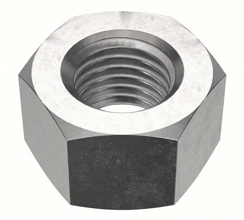
Knowing what macros are and what they are capable of will help you to use them in an effective and profitable way. Macros serve as just an other method to achieve a certain goal. Here is an example that I want to mill the hex nut on the lathe using live tooling. If you need to change both feedrate and depth of cut in the program, the change has to be done for each flat individually. With many flats, this could be a time consuming task. A macro feature used in the program greatly simplifies the job.
%
O0996
(PROGRAMMER: FRANCIS NGUYEN)
(VERSION: 2023)
(HEX MILLING WITH MACROS)
(T6 2" FACEMILL)
G54 G18 G20
G28 U0.
G00 Z5.
M35 (SPINDLE STOP C-Axis)
G40 G98 T0606 (Feed per minute)
(MILL ALL 6 SIDES OF HEX)
#100 = 0.
WHILE [#100 LT 360.] DO1 (WHILE LOOP TERMINATES WHEN #100 > 360)
G00 C#100
G00 X2.9 Z.125 M08
G97 S460 M03 P12 (Live Tool Spindle Speed/Live Tool Drive Forward)
G71 U.05 R.1 (0.1 DEPTH OF CUT)
G71 P51 Q52 U0. W0. F6.15
N51 G00 X2.53
G01 Z-2.
N52 G00 X2.9
#100 = #100 + 60. (INCREMENT BY 60)
END1
G28 U0. M09
G00 Z5.0
M05 P12 (LIVE TOOL SPINDLE STOP)
M34 (SPINDLE REVERSE C-Axis)
T0600
M30
%
%
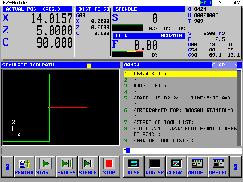
O0995
(PROGRAMMER: FRANCIS NGUYEN)
(VERSION: 2024)
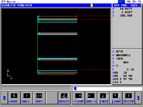
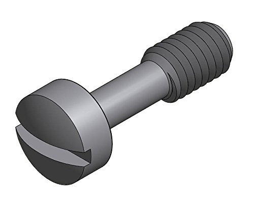
(SLOT MILLING WITH MACROS)
(T9 3/32" FLAT ENDMILL)
G54
G0 Z5.
G28 U0.
G18
G00 G40 G98 T0909 (Feed per minute)
M35 (SPINDLE STOP C-Axis)
G0 C90.
G0 X.15625 Z.5 M08
G97 S2500 M03 P12 (Live Tool Spindle Speed/Live Tool Drive Forward)
(SLOT WITH .015 DEPTH OF CUT)
#100 = -.015
WHILE [#100 GT -.145] DO1 (WHILE LOOP TERMINATES WHEN #100 < -.145)
G00 Z.1
X.2222
C90.
Z#100
G01 X-.2222 F.5
#100 = #100 - .015 (DECREMENT BY .015)
END1
G00 Z5.
G28 U0.
M05 P12(LIVE TOOL SPINDLE STOP)
M34 (SPINDLE REVERSE C-Axis)
M09
M30
%
C-Axis Turning and Live Tooling
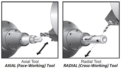
The C-axis machine tool combines the best elements of a lathe and a milling machine to turn out complex parts quickly that would be much less productive if done as multiple ops across different machines. First, it has the ability to treat the spindle as another axis, called the C-Axis. This allows positioning the part with great position to any angle. Second, it has live tooling. Instead of an ordinary lathe tool in a turret position, there’s a miniature motorized spindle that can hold endmills, twist drills, saws, or whatever else is needed.
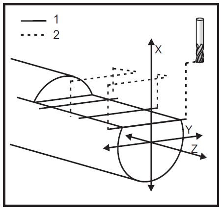
Milling Flats with Y Axis for Haas
%
002003
N20
(MILL FLAT ON DIAMETER 3.00 DIAMETER .375 DEEP)
T101 (.750 4 FLUTE ENDMILL)
G19 (SELECT PLANE)
G98 (IPM)
M154 (ENGAGE C-AXIS)
G00 G54 X6. C0. Y0. Z1 . (RAPID TO A POSITION)
G00 C90. (ROTATE C AXIS TO 90 DEGREES)
M14 (BRAKE ON)
G97 P3000 M133 (LIVE TOOL ON)
G00 X3.25 Y-1.75 Z0. ( RAPID POSITION)
G00 X2.25 Y-1.75
M08
G01 Y1.75 F22.
G00 X3.25
G00 Y-1.75 Z-0.375
G00 X2.25
G01 Y1.75 F22.
G00 X3.25
G00 Y-1.75 Z-0.75
G00 X2.25
G01 Y1.75 F22.
G00 X3.25
G00 X3.25 Y0. Z1.
M15 (BRAKE OFF)
M135 (LIVE TOOL OFF)
M155 (DISENGAGE C-AXIS)
M09
G00 G28 H0.
G00 X6. Y0. Z3.
G18 (RETURN TO NORMAL PLANE)
G99 (IPR)
M01
M30
%
Milling 2.4 Hex on 2.5" Diameter Round Stock for Haas

%
000101
( MACHINE WITH G58 )
( MILL SINGLE END)
G00 G40 G99
G53 G00 X0.
G53 G00 Z-5.
T909 ( 1.0 DIA. 3FL. E.M. ) ( ER-32 RADIAL HOLDER )
G19 (SELECT PLANE)
M154 ( ENGAGE C-AXIS )
G28 H0.
M133 P2650 (LIVE TOOL ON)
G98
G58 G00 Z0. C0.
G58 G00 X3.5
G58 G00 Y-1.25
( C0.0 )
G01 X2.4 F20.
G01 Y1.25 F10.
G00 X3.5
( C60.0 )
G00 Y-1.25 C60.
G01 X2.4 F20.
G01 Y1.25 F10.
G00 X3.5
( C120.0 )
G00 Y-1.25 C120.
G01 X2.4 F20.
G01 Y1.25 F10.
G00 X3.5
( C180.0 )
G00 Y-1.25 C180.
G01 X2.4 F20.
G01 Y1.25 F10.
G00 X3.5
( C240.0 )
G00 Y-1.25 C240.
G01 X2.4 F20.
G01 Y1.25 F10.
G00 X3.5
( C300.0 )
G00 Y-1.25 C300.
G01 X2.4 F20.
G01 Y1.25 F10.
G00 X3.5 Z2. M09
G28 W0. H0.
G99 M135 (LIVE TOOL OFF)
M155 (DISENGAGE C-AXIS)
G53 G00 X0.
G53 G00 Z-5.
G18 (RETURN TO NORMAL PLANE)
M30
%
B-Axis Turn/Mills
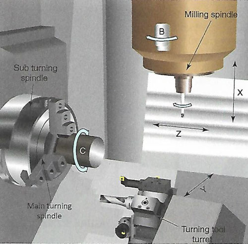
The B-axis machine tool combines the turning capabilities of a horizontal/vertical turning machine with the milling and machining capabilities of a five-axis machining center. Like traditional turn/mill machines, B-axis machine tools provide control over the Z-X (turning) and C (rotary milling) axes. The B-axis head is used as a milling spindle or a turning/boring toolholder, thus enabling the machine to complete all milling and turning with one setup. These machine tools also give users control over the Y-axis for off-center milling operations. However, it is B-axis capability that sets these machines apart. The B axis is defined as rotation about the Y axis, and this fifth axis positioning makes cuts with compound angles possible. B-axis capability gives a machine full support for five-axis index milling and 3D/five-axis simultaneous freeform milling. The B-axis machine is literally one machine doing the work of two because it supports the entire range of milling and turning operations possible, with the advantage of doing it in one setup. With these machines a finished part can be produced from raw material without ever leaving the machine.
Swiss-Type Turning Center
Swiss crew machines were developed in Switzerland for producing small parts using in watches. Today, these turning machines have full CNC controls and make all sorts of small parts for medical, electronics. defense, and other industries. Swiss machines are unique because the workpiece is supported at all times by guide bushing and stabilize it and prevent it from deflecting and vibrating. Instead of moving the tool, the entire part moves in the Z-axis direction while supported by the guide bushing. Many Swiss machines such as Citizen hold the tools in a side-by-side arrangement on multiple machine slides that can be moved separately from one another to increase productivity.
Five-Axis Programming
Most five-axis programs are rather complex and should be written using a CAD/CAM software package such as SolidWorks/MasterCam. It is necessary to determine the pivot length and gauge length of the machine, and input them in these programs.
Create the CAD drawing is the first step in computer aided manufacturing so that its geometry may later be used for creating the machining operations. After a drawing has been created, the next step in CAM is to define the toolpath, or the path that the tool will follow in order to machine the part.
Three-dimensional surface milling is an area where the CAM software really begins to demonstrate its potential. Without CAM software, all but the simplest surface toolpaths would be virtually impossible. The final step in CAM programming is to take all of the defined toolpath data and allow the CAM software to write a CNC program.
Machining simulation that works perfectly in the virtual environment may not work physically without careful planning and consideration. Some of the major factors include choosing adequate fixtures to firmly hold the stock to the jig table, checking to ensure that cutters would not collide with fixtures and jig table, and verifying that the syntax and semantics of the G-code are compatible with the CNC machine at the shop floor.
Conversational-Type Programming
Not all CNC machines must be programmed with G- and M-codes. Some machines have a special type of MCU that allows conversational programming. Conversational programming was developed to simplify the machine programming process. There are many different types of conversational MCU brands, including Southwest Industry's Proto-TRAK machines, Bridgeport's EZ-Trak, Fanuc's FAPT and CAP, and Mazak's Mazatrol controls.
The advantages are that it requires much less programming knowledge, can often be faster for simple features, and can easily be performed at the machine on the shop floor. The disadvantages revolve mostly around the lack of flexibility: the only operations that can be performed are those provided by the manufacturer. It is for these reasons that conversational controls are usually most useful for repair work, prototyping, or low-volume production machines. When high production quantities require highly efficient programs or complex machining scenarios, the versatility of a G- and M-code programming method is usually more suitable.
SOLIDWORKS vs Mastercam
Both Mastercam and SOLIDWORKS can create model geometry and generate NC code. For 3D modeling, SOLIDWORKS is the world’s most widely used design software for a reason. It has a clear advantage for anyone routinely performing the design of products or fixtures.
- The SOLIDWORKS User Interface is highly optimized for modeling, with slick contextual menus and intelligent sketch snapping and dimensioning. It makes quick work of generating the exact model geometry you need, and parametric geometry makes quick work of design changes.
- SOLIDWORKS is everywhere and is easy to learn. Previous SOLIDWORKS or parametric CAD users will find using the Mastercam Design to be frustrating to use beyond small design changes and edits.
- Mastercam doesn’t use sketch relations and constraints. Therefore, design changes tend to be a bit harder to perform.
For CNC programming, Mastercam is the World’s #1 CNC Programming software for a reason. It is powerful and easy to use and supports a wide range of machines and technologies.
- Mastercam can go beyond simple 3-axis mill and 2-axis lathe. It can program highly advanced multi-axis machines.
- SOLIDWORKS CAM is somewhat limited. It does not support local milling and contour surface milling operations.
- SOLIDWORKS CAM requires 3D feature creation/recognition before toolpaths can be generated, where Mastercam can optionally create toolpaths on just about anything from sketches and wireframes to surfaces and solids for a more flexible programming approach.
SOLIDWORKS CAM is a low-cost option for users whose primary needs are design rather than manufacturing, but Mastercam offers a breadth and depth of features that cannot be matched for machine shops and programmers.
Geometric Dimensioning and Tolerancing (GD&T)
Modern manufacturing requires more preciseness or exactness in the design and production of pars than formerly required. For the last few decades, industry has been using an advanced system of print annotation known as geometric dimensioning and tolerancing (GD&T) to control the quality of mass-produced parts with a system of geometric control symbols, feature control frames, basic dimensions, and modifiers.

