The engine lathe is one of the most versatile and oldest machine tools in the machining field. The principal operation of the engine lathe is to rigidly hold and rotate a workpiece against a cutting tool. The tool travels along the outside of the workpiece to shave off material and produce cylindrical parts.
Speed
The standard formula for used for lathe operations: RPM = 3.82 X CS / D where CS = cutting speed in surface feet per minute and D = diameter of the workpiece.
Feed
Feed rates for lathe operations are given in IPR (inches per revolution), or FPR (feed per revolution in inches). For example, the feed rate of 0.002 IPR (or FPR) means that every time the spindle makes one revolution, the cutting tool advances 0.002" across the surface of the work.
Time
Calculate time per cut = L / (RPM X IPR) where L is the length of the workpiece
Project 1 - Short Shaft
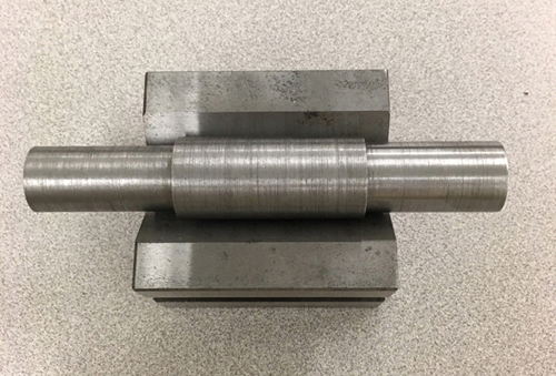
Facing and turning are two of the most common lathe operations. Facing is cutting across the end of a workpiece to machine the end flat, while turning is reducing the outside diameter of a workpiece. Avoiding excessive tool overhang provides a rigid setup and eliminates chatter or vibration. Follow these steps to machine turning operations:
- Center drill both ends so we can use the tailstok to secure the Morse taper or other workholding accessories to help support the workpiece in many operations.
- Rough at 0.010 IPR and finish at 0.001 IPR.
- Take as many cutting passes as needed speeds, and heavy feed rates. During roughing, the length and diameter can be checked with dial caliper since greater accuracy is not needed. Then increase speed and take lighter cuts at lower feed rates for finishing the diameter to the desired size. Use an appropriate measuring tool such as a micrometer to measure the work during the finishing stage.
- Face off both ends of the workpiece to the desired length.
Project 2 - Long Shaft
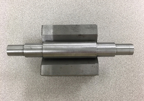
Use the same operations as project 1. Note that the tolerance for the diameters is now 0.002 instead of 0.005.
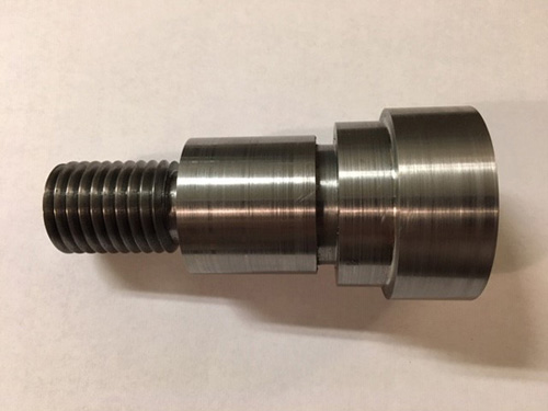
Project 3 - Angle Shaft
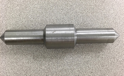
Shouldering combines turning and facing to create a step where two different diameters meet. The compound rest can be positioned to machine to angular shoulder or taper.
Project 4 - Turning Between Centers
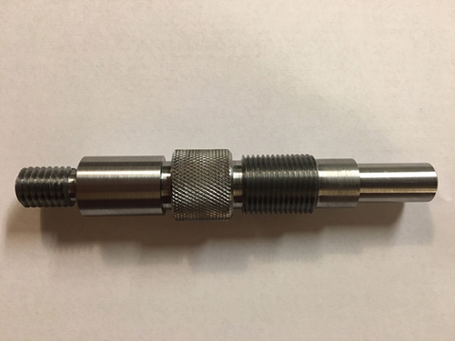
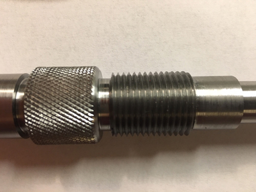
Threading ¾-16 UNF-2A
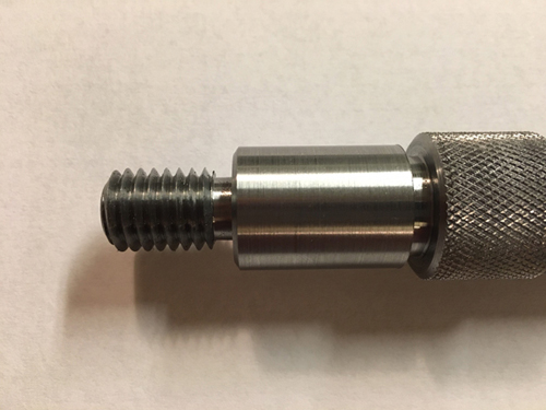
Threading ½-13 UNC-2A
- Tools:
- Center drill
- Inserted carbide roughing tool
- Inserted carbide finishing tool
- Grooving tool
- Chamfering tool
- Bump type knurling tool
- External thread cutting tool
- Dimension: 0.9” OD X 5.12” L
- RPM:
- Roughing: 350 RPM
- Finish: 700 RPM
- Grooving: 80 RPM
- Threading: 80 RPM
- Knurling: 80 RPM
- Filing/Sanding: 160 RPM
- Material: cold roll steel or mild steel
- Operations:
- Facing
- Roughing
- Finishing
- Shoulder Lengths
- Undercutting
- Threading
- Knurling
- Filing/Sanding
- Facing
The facing operation is usually one of the first operations to be performed on a turned workpiece. The purpose of this operation is to produce a flat surface perpendicular to the part center line to serve as the part face. This surface usually established the Z-axis zero location (Z0), and all other surfaces will be referenced from it.
- Turning
- Center drilling both ends. Use the tailstock to see if the center drill is center. If the drill produces a high-pitched squealing sound and/or fine stringy chips, the feed rate should be increased. If the chips are purple or blue, the feed should be reduced. Improper speed or feeds can cause the tip to become very hot. This can lead to drill breakage.
- Measure the overall length of the workpiece with the height gage.
- Use Lathe Center for roughing and finish. The main advantage of working between centers is that work can be easily removed, turned end for end, and reinstalled with a very high level of repeatability, or accuracy. Diameters machined from each end will maintain concentricity and have very little runout because the centers accurately locate the work in the same position each time.
- Perform rough cutting passes to remove as much material as quickly as possible to get close to the desired size. After roughing, finishing is used to produce a smoother surface and bring the part to the final desired size.
- Finish Grooving: Reduce the RPM for the grooving operation. This undercut is a narrow groove that provides a space for the threading tool to stop after the half-nut lever is disengaged without damaging the threads.
- Chamfer
- Threading ¾-16 UNF-2A
- Threading ½-13 UNC-2A
-
External Threading Lathe Setup:
- Use flank infeed method
- Applying a coating of layout fluid to the workpiece diameter can make it easier to make a light touch.
- The quick-change gear box and carriage feed direction will need to be properly set up so that the cutting tool feeds appropriately during cutting.
- If the right-hand threads are to be produced, the lathe spindle should rotate forward while the carriage advances longitudinally toward the headstock.
- When threading, one hand should be on the half-nut lever, and the hand on the cross-feed hand wheel.
- Threading RPM is typically 1/4 of the turning speed.
- Always select an RPM you are comfortable with, so you have time to react when necessary.
- Use the center gage to align the thread-cutting tool’s form to the workpiece.
- The cross-slide and compound-rest hand-wheel collars may then be set to “0” while in this position. Also set X-axis to “0” on the DRO.
- When threading, the half-nut lever is used. Half-nut dials will be marked with a 1, 2, 3, and 4.
- It is a good idea to take a few “spring” passes without advancing the compound rest.
- The compound-rest should be used to advance the cutting tool only 0.001” – 0.002” for the first pass.
- Use a thread pitch gage to check if the scratch cut of threads lines up correctly.
- As the spindle rotates under power, the half-nut lever is engaged at the proper time as indicated by the threading dial to begin the cutting pass. The threading dial must be watched closely so that the half-nut lever is engaged at the appropriate time. When the tool arrives at the end of the threaded section, the half-nut lever is disengaged. Then the cross-slide hand wheel should be rotated one full turn to retract the tool out of the threaded groove. As the threading tool becomes engaged deeper in successive cuts, reduce the in-feed to about 0.002” per pass. Final finish passes should be around 0.0005” to 0.001” in depth. It is a good idea to set the cross-slide hand-wheel lever at 9 o’clock position when cutting external threads. This makes it easier to retract the tool by simply pushing the lever in downward motion and can help to prevent accidentally moving the cross slide in the wrong direction when retracting the tool.
Determine thread data for ¾-16 UNF-2A Major diameter: Max = 0.7485 Min = 0.7391 Pitch diameter: Max = 0.7079 Min = 0.7029 Wire thread gage: M = E + constant = 0.7029 + 0.06587 = 0.76877 Determine thread data for ½-13 UNC-2A Major diameter: Max = 0.4985 Min = 0.4876 Pitch diameter: Max = 0.4485 Min = 0.4435 Wire thread gage: M = E + constant = 0.4435 + 0.06838 = 0.51188
- Knurling
- A knurl provides a gripping surface on handles, knobs, or levers.
- A knurling operation is done at a low RPM and feed 0.050.
- Use the bearing center on the tailstock for support while knurling.
- The feed should be set to a fairly coarse feed. This helps the knurl rollers to track properly. (i.e. .030" per revolution)
- The raised pattern causes the workpiece diameter to increase after knurling. A medium diamond knurl will increase workpiece diameter by about 0.020”.
- Filing/Sanding
- Run the spindle at about 160 RPM.
- Filing/sanding should only be used to break sharp edges.
Project 5 - Turning Operation
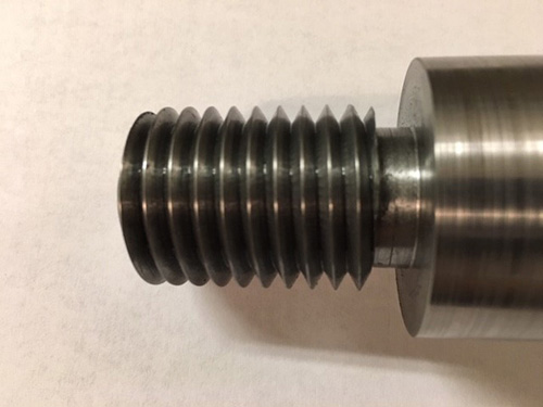
Threading 1.000-8 UNC-2A
Threading 1.250 -12 UNF-2B
- Tools:
- Center drill
- Inserted carbide roughing tool
- Inserted carbide finishing tool
- Grooving tool
- Chamfering tool
- External thread cutting tool
- 0.500” drill
- 0.750” drill
- Boring bar
- Internal grooving tool
- Internal thread cutting tool
- Dimension: 1.950” OD X 4.30” L
- RPM:
- Roughing: 350 RPM
- Finish: 700 RPM
- Grooving: 80 RPM
- Threading: 80 RPM
- Filing/Sanding: 160 RPM
- Material: cold roll steel or mild steel
- Operations:
The lathe project will require two setups.
The first setup for the following external operations:
- Facing
- Roughing
- Finishing
- Shoulder Lengths
- Undercutting
- External Threading
- Filing/Sanding
- Drilling The second setup will use soft jaws for the following internal operations:
- Boring
- Undercutting
- Internal threading
- Turning
- Indicate and center drilling both ends
- Measure the overall length of the workpiece with the height gage
- Use Lathe Center for roughing and finish
- Finish Grooving Reduce the RPM for the grooving operation.
- Chamfer
- Threading 1.000-8 UNC-2A
- Filing/Sanding Run the spindle at about 160 RPM.
-
Determine thread data for 1-8 UNC-2A Major diameter: Max = 0.9980 Min = 0.9830 Pitch diameter: Max = 0.9168 Min = 0.9100 Wire thread gage: Use wire size 0.072 M = E + constant = 0.9100 + 0.10775 = 1.01775
-
Peck Drilling Some lathes may have graduations on the tailstock quill or hand wheel. A lower RPM will allow you to clear and buildup of chips. Peck drilling is the process of clearing the drill from the part to clear out chips.
- Center drilling 0.440
- Spot drilling 0.500
- Twist drilling 0.720
-
Clamping workpiece with soft jaw inserts Soft jaws will be placed between the workpiece and the jaws of the chuck to prevent marking the part during machining.
-
Boring Bore the hole for a 1.250 -12 UNF-2B Minor diameter = 1.160
- Rigidity is a prime concern when boring, so use the largest boring bar as possible.
- The longer a boring bar hangs over the tool holder the more it will flex causing unwanted chatter. Keep the length of the bar as short as possible to minimize vibration, but be sure it is long enough to reach the desired depth without chance of collision between the toolholder and the workpiece.
- If chatter occurs, increase the feed rate and reduce spindle speed.
- The boring bar should be setup as rigid as possible.
- Zero the tool on the face of the of the part.
- Take a check cut, measure, and put that dimension in the DRO.
- Use a telescoping gage and a micrometer to measure the bore size.
-
Internal Grooving Reduce the RPM for the grooving operation. To machine an undercut for a thread relief, use an internal grooving bar.
-
Chamfering
- Internal Threading
- Applying a coating of layout fluid to the workpiece diameter can make it easier to make a light touch.
- The quick-change gear box and carriage feed direction will need to be properly set up so that the cutting tool feeds appropriately during cutting.
- Choose a threading bar as short as possible, still having proper clearance.
- Be very careful when internal threading to a blind shoulder, and slow down the RPM.
- Use the center gage to align the thread-cutting tool’s form to the workpiece.
- If the right-hand threads are to be produced, the lathe spindle should rotate forward while the carriage advances longitudinally toward the headstock.
- The cross-slide and compound-rest hand-wheel collars may then be set to “0” while in this position. Also set X-axis to “0” on the DRO.
- It is a good idea to set the cross-slide hand-wheel lever at 3 o’clock when cutting internal threads. This makes it easier to retract the tool by simply pushing the lever in downward motion and can help to prevent accidentally moving the cross slide in the wrong direction when retracting the tool.
- When threading, one hand should be on the half-nut lever, and the hand on the cross-feed hand wheel.
- Take a scratch cut, shut the machine down, and check pitch with a thread pitch gage.
- When necessary, in between cuts, stop the machine and remove chips.
Determine thread data for 1.250 -12 UNF-2B Minor diameter: Max = 1.178 Min = 1.160 Pitch diameter: Max = 1.2039 Min = 1.1959