There is no standardized format for writing a CNC program that is compatible with all machine control models. Each MCU manufacturer has developed its own unique programming format. Each one has minor differences, but the principles contained in the context of a program are the same among them all. These programs that I have written for school projects will relate most closely to Fanuc-type controllers specifically Haas; however, the principles may be applied to any manufacturer's programming format (see the specific machine's programming manual).
Free download from Haas:
Free download from Doosan:
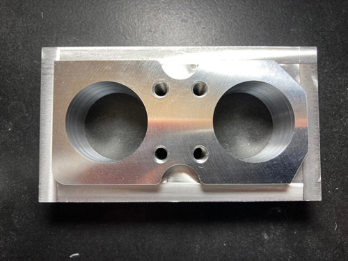
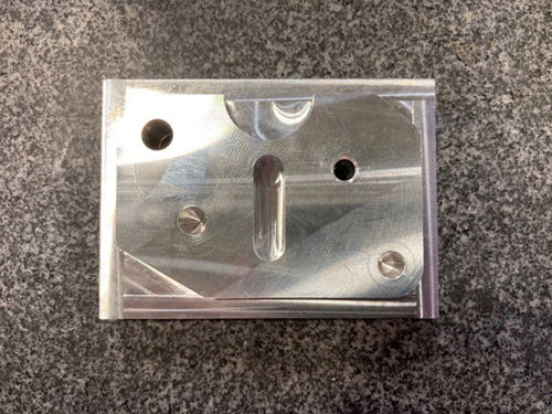
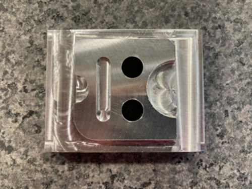
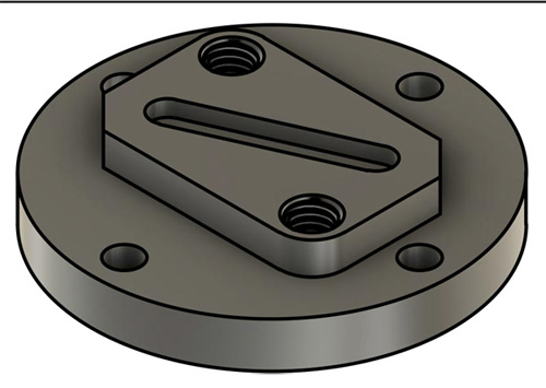
I have several projects per semester. By the end of the semester, I have created many programs and machined the entire things and that really is inspirational. Here are some of the projects I have done in the shop.
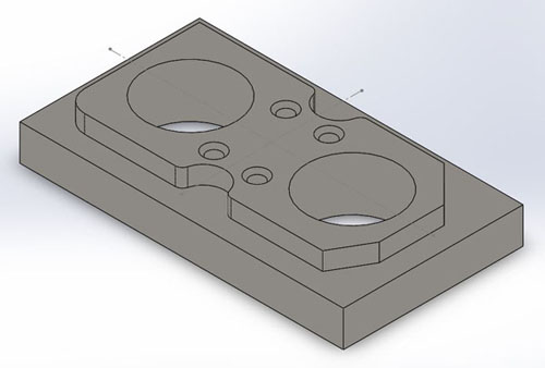
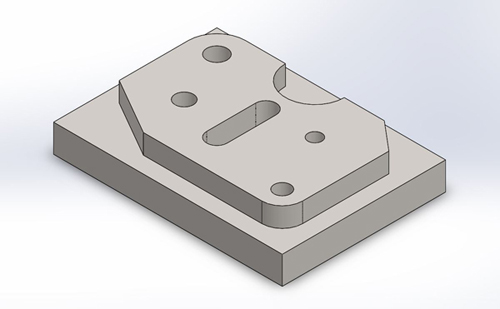
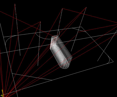
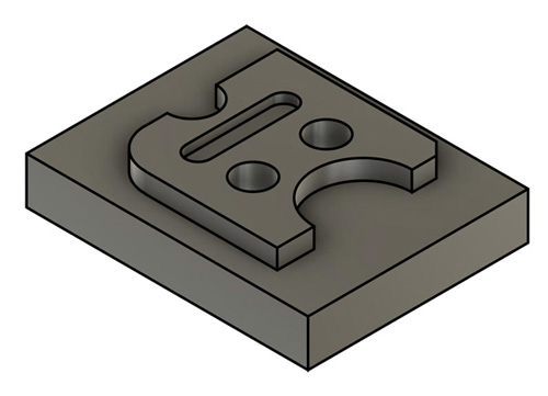
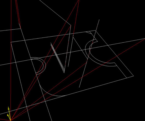
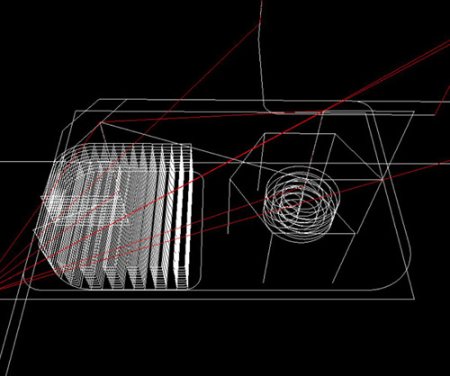
Circular Pocket Milling
This G13 code implies the use of G41 cutter compensation left and will be machining in a counterclockwise direction. G13 is usually preferred instead of G12, since G13 will be climb cutting when used with a standard right handed tool.
For Haas CNC Milling Machines
%
O00100
(PROGRAMMER: FRANCIS NGUYEN)
(VERSION: 2020)
(STOCK 4.5" X 2.5" X 0.75")
(1ST QUADRANT)
(T1 3" FACEMILL)
(T2 1/2" FLAT ENDMILL 0.500" dia)
(T3 1/2" SPOT DRILL)
(T4 #7 DRILL 0.201" dia)
(T5 1/4-20 UNC TAP 0.250" dia)
(T6 1/2 DRILL 0.5" dia)
(FACE TOP CLEAN)
(T1 3" FACEMILL)
G00 G40 G49 G80 G90
T1 M06 (T1 3" FACEMILL)
S1200 M03 (SET SPINDLE SPEED TO 1200 RPM)
G90 G54 G00 X-2.0 Y1.25
G43 H01 Z1.0 (RAPID TO 1.0 ABOVE PART)
G01 Z0. F28.0 M08 (COOLANT ON)
X7.1
G00 Z1. M09
G53 G49 Z0. M05
M01
(CENTER DRILL 4 TAP HOLES)
(T3 1/2" CENTER DRILL 0.500" dia)
T3 M06
S1200 M03 (SET SPINDLE SPEED TO 1200 RPM)
G90 G54 G00 X1.95 Y0.75
G43 H03 Z1.
G01 Z.1 F25. M08
G81 G99 Z-.125 R.1 F6.0 L0 (G99 R PLANE)
M98 P10000 (Subprogram call)
G80 G00 Z1.0 M09
G53 G49 Z0.0 M05
M01
(DRILL THRU FOUR 1/4-20 HOLES)
(T4 #7 DRILL 0.201")
T4 M06 (T4 #7 DRILL 0.201")
S1200 M03 (SET SPINDLE SPEED TO 1200 RPM)
G90 G54 G00 X1.95 Y0.75
G43 H04 Z1.
G01 Z.1 F25. M08
G83 G99 Z-0.871 Q0.075 R.1 F6.0 L0 (G99 R PLANE)
M98 P10000 (Subprogram call)
G80 G00 Z1.0 M09
G53 G49 Z0.0 M05
M01
(CENTER DRILL 2 POCKET HOLES)
(T3 1/2" CENTER DRILL 0.500" dia)
T3 M06
S1200 M03 (SET SPINDLE SPEED TO 1200 RPM)
G90 G54 G00 X1.125 Y1.25
G43 H03 Z1.
G01 Z.1 F25. M08
G81 G99 Z-.2 R.1 F6.0 (G99 R PLANE)
X3.375
G80 G00 Z1. M09
G53 G49 Z0. M05
M01
(DRILL THRU 2 HOLES)
(T6 1/2 DRILL 0.5" dia)
T6 M06
S1200 M03 (SET SPINDLE SPEED TO 1200 RPM)
G90 G54 G00 X1.125 Y1.25
G43 H06 Z1.
G01 Z.1 F25. M08
(Q - PECKING EQUAL INCREMENTAL DEPTH AMOUNT)
G83 G99 Z-1.05 Q0.075 R.1 F6.0 (G99 R PLANE)
X3.375
G80 G00 Z1. M09
G53 G49 Z0. M05
M01
(CONTOUR & CUT AROUND THE PERIMETER)
(T2 1/2" FLAT ENDMILL 0.500" dia)
T2 M06 (T2 1/2" FLAT ENDMILL 0.500" dia)
S4000 M03 (SET SPINDLE SPEED TO 4000 RPM)
(1ST PASS ROUGHING)
G90 G54 G00 X-1.0 Y-1.0 (STARTING X Y )
G43 H02 Z1.0
G01 Z.1 F30.0 M08 (COOLANT ON)
Z-0.25 (FEED TO FINAL DEPTH)
G41 D02 X0.3 (START BOTTOM LEFT)
Y2.2 (POINT 2 ROUGHING)
X4.2 (POINT 7 ROUGHING)
Y0.3 (POINT 9 ROUGHING)
X-1. (POINT 15 ROUGHING)
Z.1
G00 Z1.0 M09
(2ND PASS FINISH)
G01 Y-1.0 M08 (COOLANT ON)
Z-0.25 (FEED TO FINAL DEPTH)
X0.3 (START BOTTOM LEFT)
Y2.2 (POINT 2 FINISH)
X1.863 (POINT 3 FINISH)
G02 X1.96 Y2.125 R0.1 (POINT 4 FINISH)
G03 X2.54 R0.3 (POINT 5 FINISH)
G02 X2.637 Y2.2 R0.1 (POINT 6 FINISH)
G01 X3.7 (POINT 7 FINISH)
X4.2 Y1.7 (POINT 8 FINISH)
Y.8 (POINT 9 FINISH)
X3.911 Y.3 (POINT 10 FINISH)
X2.637 (POINT 11 FINISH)
G02 X2.54 Y0.375 R0.1 (POINT 12 FINISH)
G03 X1.96 R0.3 (POINT 13 FINISH)
G02 X1.863 Y0.3 R0.1 (POINT 14 FINISH)
G01 X.6 (POINT 15 FINISH)
G02 X.3 Y0.6 R0.3 (POINT 1 FINISH)
G01 Y3. (POINT 2 EXIT)
Z.1
G40 G00 Z1. M09
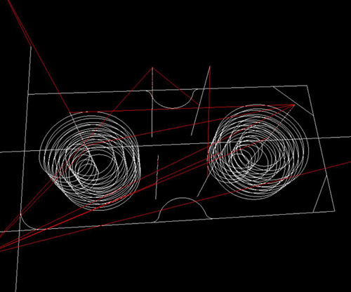
(TWO 1.25" CIRCULAR POCKET MILLING)
G00 X1.125 Y1.25 (XY POSITION TO CENTER OF CPM1)
Z0.1 M08 (RAPID TO 0.1 ABOVE PART)
G01 Z0.0
(I - Radius of the first circle and must be greater than Tool Radius)
(K - Radius of finished circle)
(L - Loop count for repeating deeper cuts)
(Q - Radius increment must be used with K)
(Z - Depth of cut or increment with G91)
(Z = 1.05 depth / 5 = 0.21)
(K = 1.25 dia / 2)
(Q = K - I = 0.325 x 2 = 0.65 / L = 0.13)
G13 G91 Z-0.21 I0.3 K0.625 Q0.13 D02 F15.0 L5 (I, K, Q & G91)
G90 G00 Z1.0 (SWITCH TO ABSOLUTE, RAPID 1.0 ABOVE PART)
X3.375 (POSITION TO CENTER OF CPM2)
G01 Z0.0
G13 G91 Z-0.18 I0.3 K0.625 Q0.13 D02 F15.0 L5 (I, K, Q & G91)
G90 G00 Z0.1 M09 (SWITCH TO ABSOLUTE, RAPID 1.0 ABOVE PART, COOLANT OFF)
G53 G49 Z0. M05
M01
(TAPPING FOUR 1/4-20 HOLES)
(TAPPING HAS TO RUN 100%)
(T5 1/4-20 UNC TAP 0.250" dia)
T5 M06 (T5 1/4-20 UNC TAP 0.250" dia)
S60 (DO NOT NEED M03 FOR TAPPING)
G90 G54 G00 X1.95 Y0.75
G43 H05 Z1.
G01 Z.1 F25. M08
(J - TAPPING RETRACT SPEED)
(F = RPM/TPI = 60/20 = 3.0)
G84 G99 Z-0.9 R.1 J3 F3.0 L0 (CAN ALSO USE G84.1 FOR TAPPING)
M98 P10000 (Subprogram call)
G80 G00 Z1.0 M09
G53 G49 Z0.0 M05
M30
%
%
O10000 (HOLE LOCATIONS)
(PROGRAMMER: FRANCIS NGUYEN)
(VERSION: 2020)
X1.95 Y0.75 (1)
X2.55 (2)
Y1.75 (3)
X1.95 (4)
M99 (Return to main program)
%
For Doosan CNC Milling Machines
%
O00100
(CIRCULAR POCKET)
(STOCK 4.5" X 2.5" X 0.75")
(1ST QUADRANT)
(T1 3" FACEMILL)
(T2 1/2" FLAT ENDMILL 0.500" dia)
(T3 1/2" SPOT DRILL)
(T4 #7 DRILL 0.201" dia)
(T5 1/4-20 UNC TAP 0.250" dia)
(T6 1/2 DRILL 1" dia)
(FACE TOP CLEAN)
(T1 3" FACEMILL)
G00 G40 G49 G80 G90 G17 (G17 SETS PLANE SELECTION)
G91 G28 Y0. Z0. (SENDS Z & Y TO THE G28 REFERENCE POSITION)
T1 M06 (T1 3" FACEMILL)
S1200 M03 (SET SPINDLE SPEED TO 1200 RPM)
G90 G54 G00 X-2.0 Y1.25 (MOVES TO 1ST POSITION USING G54 WORK OFFSET)
G43 H01 Z1.0 (RAPID TO 1.0 ABOVE PART)
G01 Z0. F28.0 M08 (COOLANT ON)
X7.1
G00 Z1.0 M09
G91 G28 Z0.0 M05 (RETURNS HOME)
G90 (G90 ABSOLUTE MODE)
M01
(CENTER DRILL 4 TAP HOLES)
(T3 3/4" CENTER DRILL 0.750" dia)
T3 M06 (T3 3/4" CENTER DRILL 0.750" dia)
S1200 M03 (SET SPINDLE SPEED TO 1200 RPM)
G90 G54 G00 X1.95 Y0.75
G43 H03 Z1.
G01 Z.1 F25. M08
G81 G99 Z-.125 R.1 F6.0 K0 (G99 R PLANE)
M98 P10000 (SUBPROGRAM CALL)
G80 G00 Z1.0 M09 (G80 CANCELS DRILLING CYCLE)
G91 G28 Z0.0 M05 (RETURNS HOME)
G90 (G90 ABSOLUTE MODE)
M01
(DRILL FOUR 1/4-20 HOLES)
(T4 #7 DRILL 0.201")
T4 M06 (T4 #7 DRILL 0.201")
S1200 M03 (SET SPINDLE SPEED TO 1200 RPM)
G90 G54 G00 X1.95 Y0.75
G43 H04 Z1.
G01 Z.1 F25. M08
G83 G99 Z-0.871 Q0.075 R.1 F6.0 K0 (G99 R PLANE)
M98 P10000 (SUBPROGRAM CALL)
G80 G00 Z1.0 M09 (G80 CANCELS DRILLING CYCLE)
G91 G28 Z0.0 M05 (RETURNS HOME)
G90 (G90 ABSOLUTE MODE)
M01
(CENTER DRILL 2 POCKET)
(T3 1/2" SPOT DRILL)
T3 M06
S1200 M03 (SET SPINDLE SPEED TO 1200 RPM)
G90 G54 G00 X1.125 Y1.25
G43 H03 Z1.
G01 Z.1 F25. M08
G81 G99 Z-.2 R.1 F6.0 (G99 R PLANE)
X3.375
G80 G00 Z1.0 M09 (G80 CANCELS DRILLING CYCLE)
G91 G28 Z0.0 M05 (RETURNS HOME)
G90 (G90 ABSOLUTE MODE)
M01
(DRILL THRU 2 HOLES)
(T6 1/2 DRILL 0.5" dia)
T6 M06
S1200 M03 (SET SPINDLE SPEED TO 1200 RPM)
G90 G54 G00 X1.125 Y1.25
G43 H06 Z1.
G01 Z.1 F25. M08
(Q - PECKING EQUAL INCREMENTAL DEPTH AMOUNT)
G83 G99 Z-1.05 Q0.075 R.1 F6.0 (G99 R PLANE)
X3.375
G80 G00 Z1.0 M09 (G80 CANCELS DRILLING CYCLE)
G91 G28 Z0.0 M05 (RETURNS HOME)
G90 (G90 ABSOLUTE MODE)
M01
(CONTOUR & CUT AROUND THE PERIMETER)
(T2 1/2" FLAT ENDMILL 0.500" dia)
T2 M06 (T2 1/2" FLAT ENDMILL 0.500" dia)
S4000 M03 (SET SPINDLE SPEED TO 4000 RPM)
(1ST PASS ROUGHING)
G90 G54 G00 X-1.0 Y-1.0 (STARTING X Y )
G43 H02 Z1.0
G01 Z.1 F30. M08 (COOLANT ON)
Z-0.25 (FEED TO FINAL DEPTH)
G41 D02 X0.3 (START BOTTOM LEFT)
Y2.2 (POINT 2 ROUGHING)
X4.2 (POINT 7 ROUGHING)
Y0.3 (POINT 9 ROUGHING)
X-1. (POINT 15 ROUGHING)
Z.1
G00 Z1.0 M09
(2ND PASS FINISH)
G01 Y-1.0 M08 (COOLANT ON)
Z-0.25 (FEED TO FINAL DEPTH)
X0.3 (START BOTTOM LEFT)
Y2.2 (POINT 2 FINISH)
X1.863 (POINT 3 FINISH)
G02 X1.96 Y2.125 R0.1 (POINT 4 FINISH)
G03 X2.54 R0.3 (POINT 5 FINISH)
G02 X2.637 Y2.2 R0.1 (POINT 6 FINISH)
G01 X3.7 (POINT 7 FINISH)
X4.2 Y1.7 (POINT 8 FINISH)
Y.8 (POINT 9 FINISH)
X3.911 Y.3 (POINT 10 FINISH)
X2.637 (POINT 11 FINISH)
G02 X2.54 Y0.375 R0.1 (POINT 12 FINISH)
G03 X1.96 R0.3 (POINT 13 FINISH)
G02 X1.863 Y0.3 R0.1 (POINT 14 FINISH)
G01 X.55 (POINT 15 FINISH)
G02 X.3 Y0.55 R0.25 (POINT 1 FINISH)
G01 Y3. (POINT 2 EXIT)
Z.1 (MOVES TO 0.1 ABOVE THE PART)
G40 G00 Z1. M09
(TWO 1.25" CIRCULAR POCKET CYCLE)
G00 X1.125 Y1.25 (XY POSITION TO CENTER OF CPM1)
Z0.1 M08 (RAPID TO 0.1 ABOVE PART)
G01 Z0.0
(D - Circular pocket diameter)
(T - Cutter radius offset number. Do not enter the actual cutter radius with T!)
(F - Cutting feedrate for the circle machining)
Z-0.18 F15.0 (Feed-in to the depth)
G13 D1.25 T56 F15.0 (D, T & F)
G00 Z1.0 (RAPID 1.0 ABOVE PART)
X3.375 (POSITION TO CENTER OF CPM2)
G01 Z0.0
Z-0.18 F15.0 (Feed-in to the depth)
G13 D1.25 T56 F15.0 (D, T & F)
G00 Z0.1 M09 (RAPID 1.0 ABOVE PART, COOLANT OFF)
G53 G49 Z0. M05
M01
(TAPPING FOUR 1/4-20 HOLES)
(TAPPING HAS TO RUN 100%)
(T5 1/4-20 UNC TAP 0.250" dia)
T5 M06 (T5 1/4-20 UNC TAP 0.250" dia)
G95 S60 (G95 FEED PER ROTATION)
G90 G54 G00 X1.95 Y0.75
G43 H05 Z1.
G01 Z.1 F25. M08
(F = 1/TPI = 1/20 = 0.05)
M29 (RIGID TAPPING MODE)
G84 G98 Z-0.9 R.1 F.05 K0
M98 P10000 (CALL SUBPROGRAM)
G94 (CHANGE BACK TO FEED PER MINUTE)
G80 G00 Z1.0 M09 (G80 CANCELS DRILLING CYCLE)
G91 G28 Z0.0 M05 (RETURNS HOME)
G90 (G90 ABSOLUTE MODE)
M30
%
%
O10000 (HOLE LOCATIONS)
X1.95 Y0.75 (1)
X2.55 (2)
Y1.75 (3)
X1.95 (4)
M99 (Returns to main program)
%
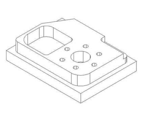
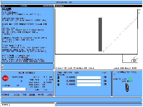
Pocket Geometry Milling
This G150 code provides for general purpose pockect milling. The shape of the pocket to be machined must be defined by series of motions within a subprogram. Make sure that the subprogram geometry is a fully closed shape. Make sure that the X-Y starting point in the G150 command is within the boundary of the fully closed shape. Failure to do so may cause Alarm 370 - Pocket Definition Error.
(G150 Shift X axis with I, milling down Q steps to Z depth)
(P Subprogram call)
(Z Final depth of pocket)
(Q Incremental Z-axis depth, starting from R plane)
(R R plane clearance position)
(I X-axis shift over cut increment)
(K Finishing cut allowance)
Text Engraving

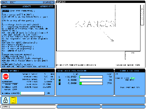
G47 lets you engrave a line of text, or sequential serial numbers, with a single G-code.
E - Plunge feed rate units/min
F - Engraving feedrate units/min
I - Angle of rotation -360. to +360. default is 0
J - Height of text in in/mm minimum = 0.001 inch default is 1.0 inch
P - 0 for literal text engraving
1 for sequential serial number engraving
32-126 for ASCII characters
R - Return plane
X - X start of engraving
Y - Y start of engraving
Z - Depth of cut
Macros
Macro programming is a part programming technique that combines standard CNC programming methods with additional control features for more power and flexibility. Macros add capabilities and flexibility to the control that are not possible with standard G-code. Some possible uses are: families of parts, custom canned cycles, complex motions, and driving optional devices. The possibilities are almost endless.
A Macro is any routine/subprogram that you can run multiple times. Macro for all CNC systems is the closest method of programming to a true language based programming, using the CNC system directly. A macro statement can assign a value to a variable, read a value from a variable, evaluate an expression, conditionally or unconditionally branch to another point within a program, or conditionally repeat some section of a program. A very important part of macros is their ability to use conditional testing, branching and looping for a very flexible program flow. The use of looping features alone, so called iteration, adds much desired extra programming power.
Macros have the potential of being extremely powerful and flexible. Macros can also shorten the programming time by many hours. In spite of their great possibilities, macros are often the forgotten gems available for CNC programming. Many companies do have macro capabilities, but avoiding them, considering them too difficult and time consuming.
Knowing what macros are and what they are capable of will help you to use them in an effective and profitable way. Macros serve as just an other method to achieve a certain goal. Here is an example that I want to mill one side from 4.8" to 4.5".
%
O00011
(PROGRAMMER: FRANCIS NGUYEN)
(VERSION: 2020)
(FACING WITH MACROS)
(4TH QUADRANT)
(T2 1/2" FLAT ENDMILL 0.500" dia)
G00 G40 G49 G80 G90
T2 M06 (T2 1/2" FLAT ENDMILL 0.500" dia)
S4000 M03 (SET SPINDLE SPEED TO 4000 RPM)
G54 X5.0 Y-3.0
G43 H02 Z1. (RAPID TO 1.0 ABOVE PART)
G01 Z.1 F25. M08 (COOLANT ON)
Z-0.855
#100 = 4.8 (NUMBERS STORED IN VARIABLE CAN BE OFF BY 1 LEAST SIGNIFICANT DIGIT)
(FACE PART TO 4.5)
WHILE [#100 GT 4.49] DO1 (WHILE LOOP TERMINATES WHEN #100 < 4.5)
G41 D02 G01 X#100 F70.
Y0.5
Y-3.0
#100 = #100 - 0.02 (DECREMENT BY 0.02)
END1
G40 X5.0
M09 (TURN OFF CC)
G00 Z1. M05
G91 G28 Z0.0
G28 G49 X0. Y0.
M30
%
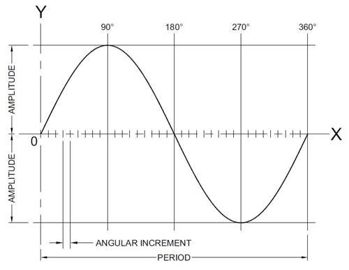
Developing a contour cutting program for a parabola, hyperbola, ellipse, sine curve, cycloid, and many other curves maybe not possible in standard CNC programs but presents no problem in macros.
The first step to take is to define the formula mathematically. Since it is a trigonometric sine curve, the SIN function will be used. Mathematically, the formula to calculate the Y is:
Y = Amplitude x sinX
Assignment of variables in the sine curve macro call O8009 is short and simple:
Amplitude . . . assigned letter A (variable #1)
Angular increment . . . assigned letter I (variable #4)
Cutting feedrate . . . assigned letter F (variable #9)
The macro call will contain only three variables:
G65 P8009 A120.0 I5.0 F250.0
Note that the current units must be used (metric shown) and the angular increment must conform to the minimum programmable input of 0.001°. In the example, the sine curve will be machined as a linear motion - a series of straight lines in increments of 5°. Decrease the increment for more accuracy, increase the increment for less accuracy. Z-axis motions must be applied in the main program. The macro will be a single level loop, using a counter of the current incremental degrees compared with the final angle, such as the 360° used in the example:
O8009 (SINE CURVE MACRO)
#25 = 0 (Set initial counter for degrees increment)
WHILE [#25 LE 360.0] (Loop for each linear segment until 360 degrees are machined)
#26 = #1 * SIN[#25] (Calculate current Y-location)
G90 G01 X#25 Y#26 F#9 (Make a linear motion to the calculated XY location)
#25 = #25+#4 (Increase the counter by specified increment)
END1 (End of loop)
M99 (End of macro)
%