Mastercam
The purpose of CAM software is to take a dimensional computerized part drawing and select features on the drawing for the tool to follow. After defining the path of the tool, the user is prompted for speeds and feeds data, depth of cut, machining patterns, and other characteristics for machining the future. Finally, all of this information is used by the PC to create a program.
The use of CAM software is not only limited to very complex programming; there are also great benefits from using such a package for basic two-dimensional contouring or even drilling operations. Even the simplest jobs can benefit from the speed and efficiency of CAM programming.
CAM programming involves there major steps to go from start to a finished program;
- Geometry creation (drawing)
- Toolpath creation
- Post-processing (creating the machine's program)
Lathe
- Lathe Face Toolpath
- Lathe Roughing Toolpath
- Lathe Finish Toolpath
- Lathe Groove Toolpath
- Lathe Thread Toolpath
- Lathe Drill Toolpath
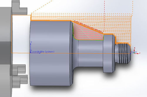
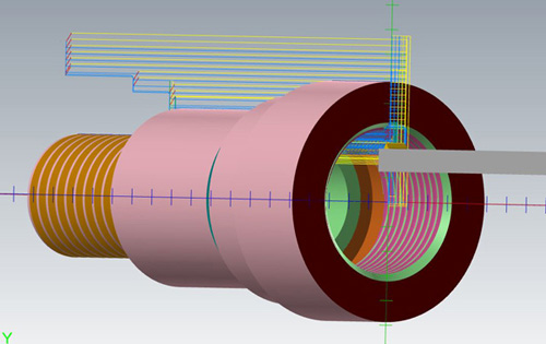
Simulate the toolpath in Verify
Verify shows the path the tools take to cut the part with the material removal. This display lets you spot errors in the program before you machine the part. It also shows any collisions between the workpiece and the tool.
Lathe: C-Axis
- The machine with only C-Axis, which is more common, provides linear motion in the X and Z axes and rotary motion around the C axis.
- C-Axis Face Contour: allows you to machine face of the part with the tool parallel to the main spindle's axis of rotation. In this case, the main spindle holding the part rotates (C-Axis) while the tool moves along the X axis. The Z axis is positioned based on the depth of the cut and the Y axis is locked in position at 0.
- Face Drilling: allows you to drill holes perpendicular to the part's spindle axis.
- C-Axis Cross Drilling: is used to drill holes that are perpendicular to the axis of rotation, as when drilling holes in a cylinder.


SolidWorks
SolidWorks is a solid modeling computer-aided design (CAD) and computer-aided engineering (CAE) computer program that runs on Microsoft Windows. Solids are usually created by first drawing 2D outline defining the part contour, and then giving that contour thickness. In addition to being visually pleasing, the solid nature of such a digital part may be very representative of the material of an actual part. For this reason, important engineering data may be gathered from a solid model drawing. Some of this data includes mass, center of gravity, volume, and how the part may fit together with other parts. Here are some of the projects I have done from a text book "SolidWorks 2016 Basic Tools".
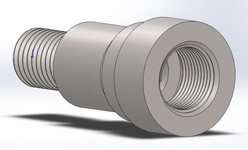
Threaded Insert
SolidWorksCam
The overall process of using SOLIDWORKS CAM for creating machining simulation consists of several steps:
- Create design model
- Choose NC machine and create stock
- Extract or identify machinable features
- Generate operation plan
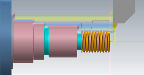
- Generate toolpath
- Simulate toolpath
- Convert toolpath to G-code through a post processor
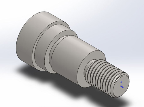
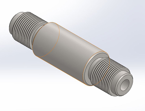
Turning a Stub Shaft